Split Charge Circuitry
I fitted a second battery under the passenger seat of Lucy-Jo (the main battery is under the bonnet). Most of the extra electrical gadgets I added to the vehicle were wired to the second battery, so that if I flattened the battery by using one of my gadgets excessively I could start start and drive the vehicle (and without resorting to the starting handle!).
The wiring I used was very simple indeed. I does have some restrictions - you can't start the vehicle from the auxiliary battery without pulling out your jump leads and manually connecting the two batteries together. Also, if you flattened the auxiliary battery, the circuitry wasn't up to charging it from flat, so the fuse would blow when you started the engine. You would then have to charge the auxiliary battery from the mains (or use jump leads to put some power back into the auxiliary battery).
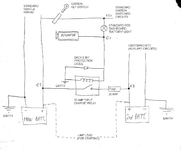
The split charge relay was wired into the red dashboard light so that the two batteries were effectively connected in parallel with one another (and the alternator) only when the ignition was switched on and the engine was running. This works because the red dashboard light only comes on when the ignition is switched on and the alternator is not charging.
The diode wired across the coil in the relay is to prevent the back electromotive field (back EMF) caused by the coil when switching on or off from damaging the coil.
If you have any questions or comments on this circuit (which I designed myself - so some people may well disagree with aspects of it) then please email me.
The relay contacts were rated for 25 Amp at 12V DC
The only connections to the existing vehicle wiring that I had to make were to the wire from the alternator to the red dashboard light (C1) with light weight wire and from the existing battery (C2) to the split charge relay (25 Amp wire). 25 Amp wire was required from the relay (through the fuse) and connecting to the second battery (C3).